The demand for fiber optics is increasing by the day, and hence it is crucial to understand the ports and network devices used here. This helps select the right devices with the required power and configuration.
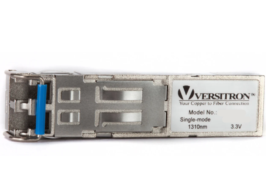
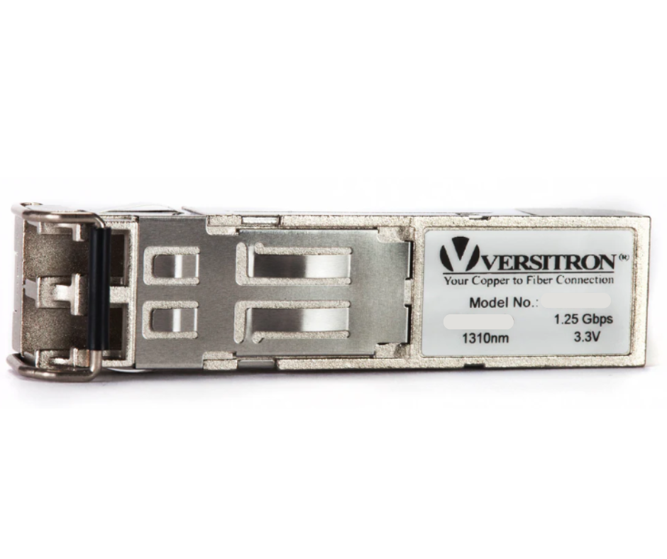
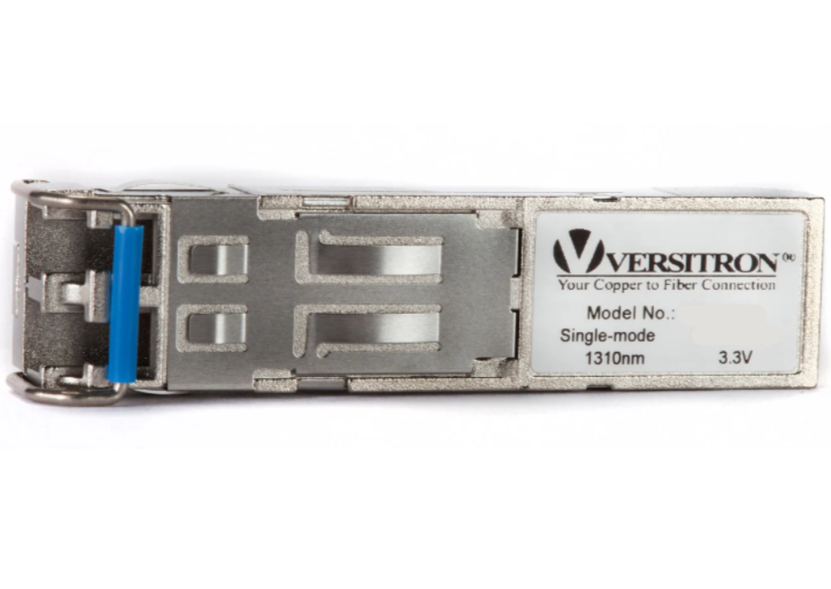
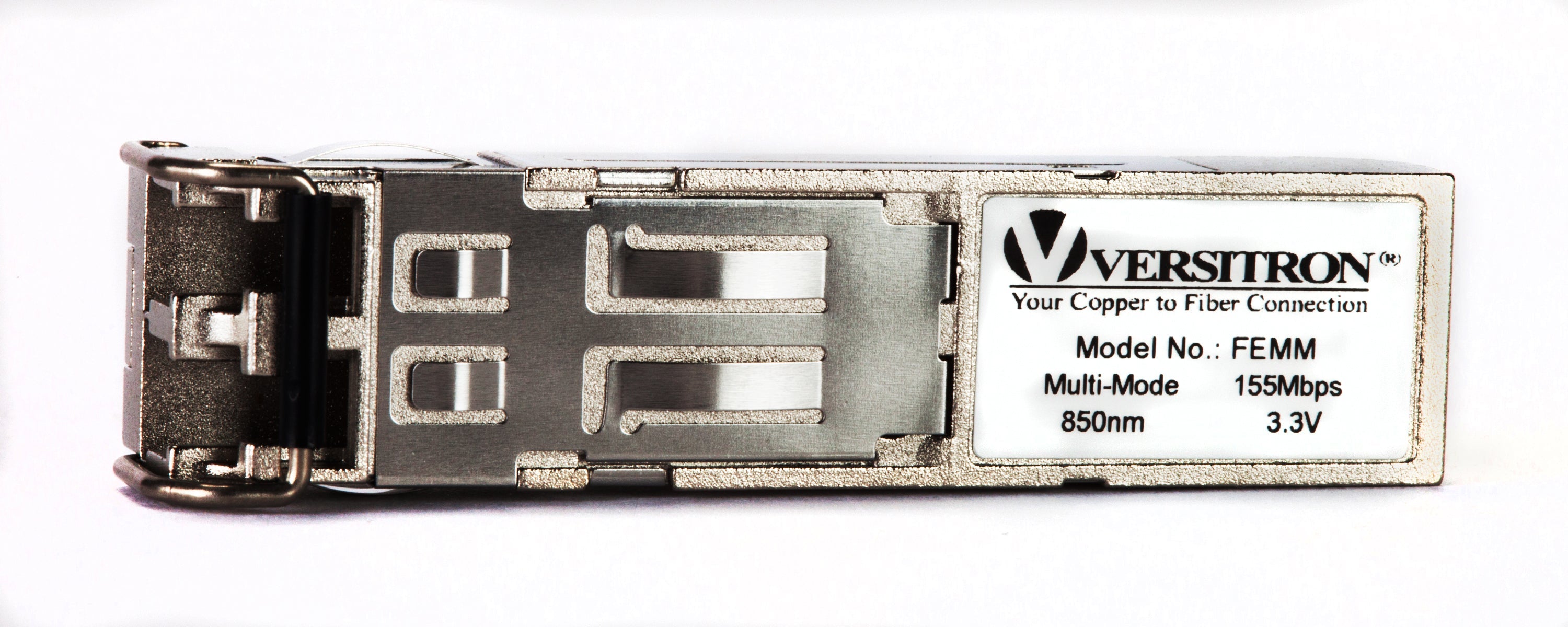
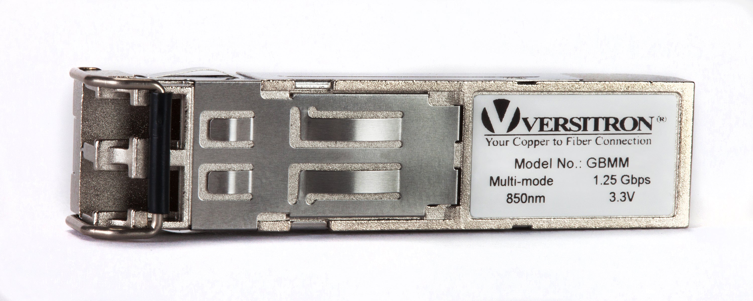
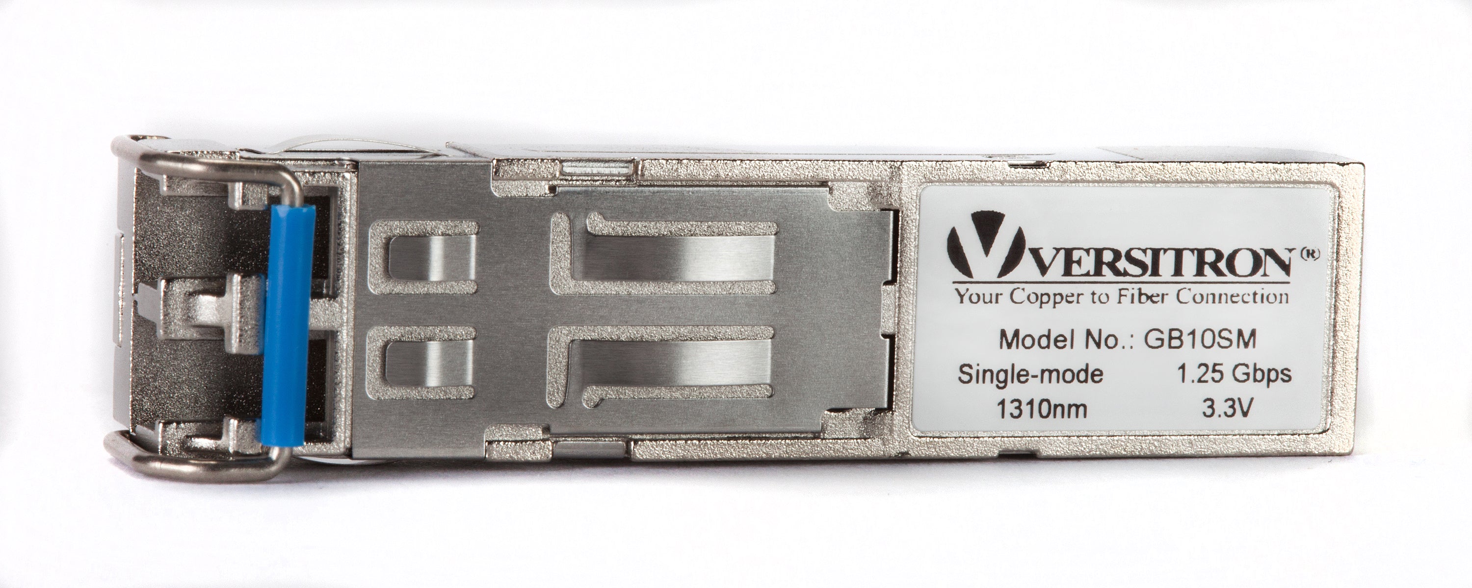
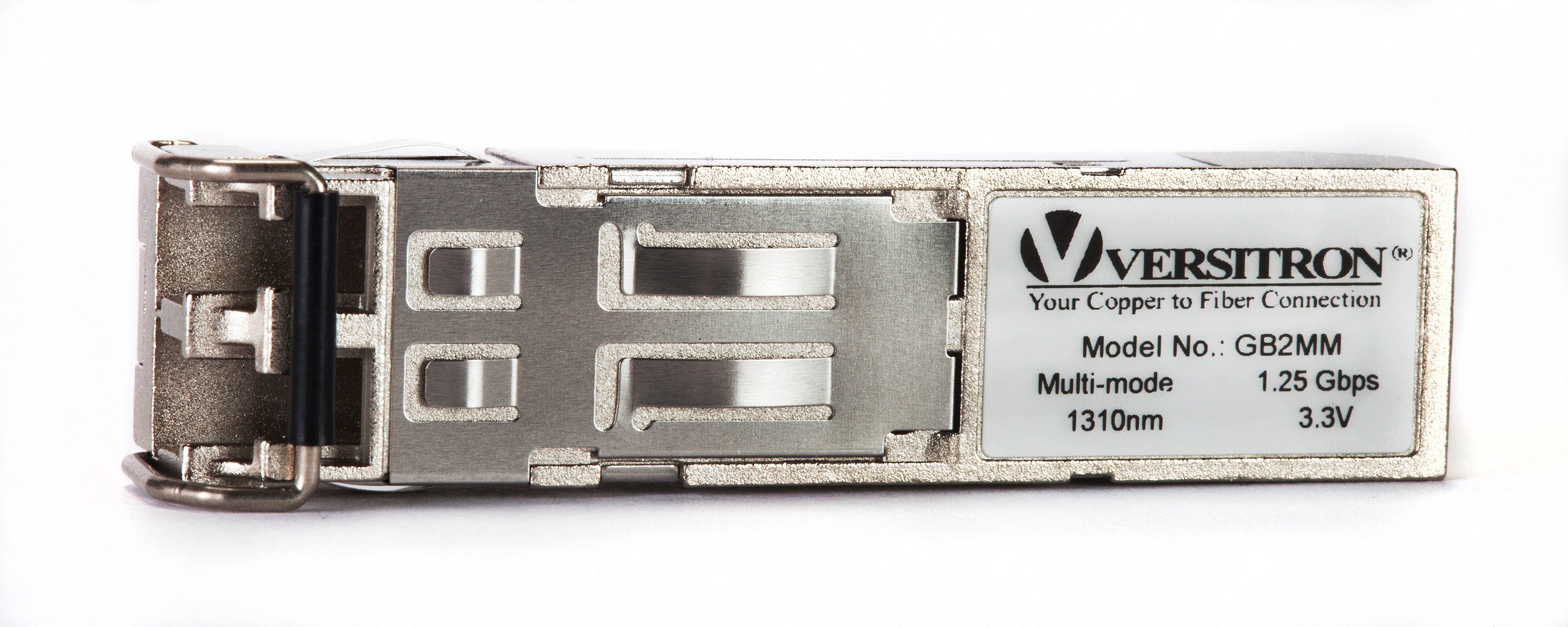
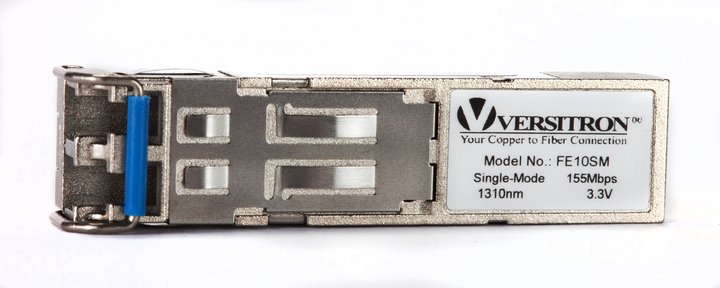
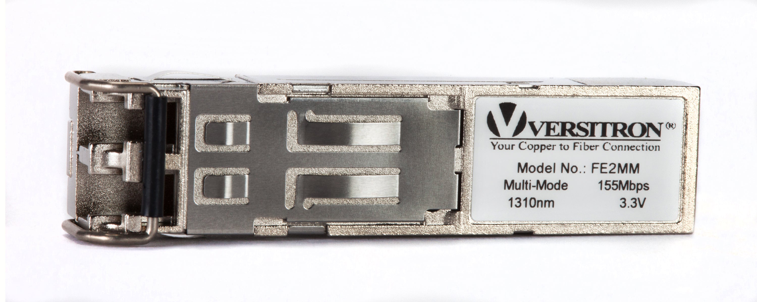
SFP modules are transceivers that can be used to connect fiber optic cables in a network. These modules are inserted into SFP ports on a switch. SFP ports are similar to RJ45 connector ports used to connect copper cables. They are used for data as well as voice communication applications and offer immediate connectivity.
RX and TX stand for receiver and transmitter sensitivity which is an important part of the optical power calculation. This post discusses the ways to identify RX/TX optical power on SFP modules.
What is RX/TX Optical Power Calculation?
Simply put, this calculation is done to find out the difference between RX or receiver and TX or transmitter sensitivity. Optical power is measured in dBm. At times, it is also measured in milliwatts or microwatts. The transmitting power leaving the transmission end device is expected to maintain signal level within the transmission range. The receiving power must be within the receiving power range and is the level of signal received from the transmitting end device. Optical power or power budget indicates the amount of light available for fiber optic connectivity. This is calculated by measuring the difference between transmitting and receiving power (TX-RX). Most switches have a command line interface and display where users can view the transceiver information such as RX power, TX power, supply voltage, and so on. Based on this data or readings, you can determine if the cable is functioning as required. The upper and lower limits for TX and RX are adjusted by manufacturers based on set standards. So, if the TX value has fallen way below the lower limit, mostly below -30 dBm, this indicates that there is no signal being transmitted over the cable.
The transceivers can be single mode as well as multimode. Multimode transceivers are designed for short distance transmission up to around 500 meters, while single mode transceivers are designed for long-distance transmission which may span a few kilometers. When calculating an optical power, the minimum value for transmitter and maximum for receiver is identified so that maximum allowable loss can be calculated.
What Are Optical Power Ranges?
Aside from the RX/TX optical power calculation, there are other factors to be considered for transmission distance, such as cable length, link length, splicing points, fiber signal attenuation, connectivity of components, and so on. A good quality transceiver would always have a high value of optical power budget. Here are optical power ranges which may indicate something specific:
- An ideal value for transmitter power is -6dBm, but it could range between -1 and -7 dBm. For receiver power, the value could range between -1 and -9 dBm.
- At times, the actual transmission may not happen, and the transmission power may fall below -25 or even -30 dBm. This may happen due to electromagnetic interference or heightened noise levels at the receiver end.
- The other scenario may be transmission power falling below -10 or even up to -15dBm. This may imply signal loss, faulty connector or cable, splicing issue.
How to Calculate Optical Power Budget by TX and RX Power?
Knowing the accurate optical power budget helps enhance the performance of signal conversion devices such as media converters which are integral to blended networks. This will provide the value for optical cable link length between two or more media converters in a network, and hence the distance for data transmission without signal losses or disruptions. This is because there must be enough energy available for its conversion into light pulses. The difference between minimum reception sensitivity and minimum transmitting power required does offer an average budget value; however, that is not an accurate output. Also, this depends on the device brands and their connection compatibility, and hence there may be variations in the optical power budget value. Here are some factors to consider when calculating this value.
- SFP TX RX power range is the minimum transmitting and receiving capacity in a fiber optic module. The higher the value of optical power budget, the more is the transmission distance.
- While one may know the amount of energy or light available, the possible losses due to connectors, splices, and so on must be considered if you want to derive the true value. The number of splices, cables, and connectors depend on the distance of transmission.
- On an average, the possible signal losses from these devices range between 0.20 and 0.7 dB depending on the type of connector or splice. This needs to be considered per connector or splice and then multiplied by the number of connectors or splices.
- Environmental factors such as extreme heat or cold may lead to signal losses and hence impact optical power budget.
- Complexities involved in the overall network must also be considered when calculating the absolute value for optical power budget.
- TX and RX power affect the performance of SFP modules in a fiber optic network.
- After all the above considerations, you can calculate power budget using a simple formula. Optical power budget = RX optical power - TX optical power
If you are a business owner looking to upgrade your network or switch to fiber optics, do consider these aspects related to optical power calculation, no of SFP ports on a switch, use of media converters in a blended network vis-à-vis your requirements and budget. Also, ensure you source these devices from a reliable and certified manufacturer and supplier. VERSITRON is a leading manufacturer and supplier of a variety of network devices such as media converters, switches with Bidirectional SFP modules and ports for RJ45 connectors, and other fiber optic devices.
FAQs
TX and RX in SFP refer to the transmission (TX) and reception (RX) of data signals over a fiber optic cable using Small Form-factor Pluggable (SFP) modules. TX converts electrical signals into optical signals while RX converts optical signals back to electrical signals. Both functions enable bidirectional communication and support various data rates and communication protocols. SFP modules provide a compact and versatile solution for fiber optic connectivity in networking applications.
SFP TX/RX power range refers to the acceptable power levels for transmitting and receiving data signals in Small Form-factor Pluggable (SFP) modules. It specifies the minimum and maximum power levels that can be used for transmitting and receiving signals without causing damage to the SFP module or the connected network equipment. The power range is typically measured in decibel milliwatts (dBm) and may vary depending on the specific type and model of the SFP module. It is important to ensure that the TX/RX power levels are within the acceptable range to maintain reliable communication and prevent equipment damage.
RX Optical Power refers to the strength of the signal received by the receiver in a fiber optic system. On the hand TX Optical Power, also known as Transmit Optical Power or TX Power measures the level of signal emitted into the fiber optic network by the optical transmitter.
The input power of a module measured in decibels referenced to one milliwatt (dBm) indicates how strong the incoming optical signal is, to the module.
If the RX (receive) optical power is too high it can cause distortion or harm to the receiver. Conversely, if it’s too low it may lead to signal loss or subpar network performance. To ensure that it falls within a range adjusting either transmitter power or attenuating the signal is recommended.
The input power of a module measured in decibels referenced to one milliwatt (dBm) indicates how strong the incoming optical signal is, to the module.
The acceptable dBm for fiber internet can vary based on factors, like the type of fiber equipment and network setup. Typically acceptable power levels fall between 3 dBm and 10 dBm.
If the RX (receive) optical power is too high it can cause distortion or harm to the receiver. Conversely, if it’s too low it may lead to signal loss or subpar network performance. To ensure that it falls within a range adjusting either transmitter power or attenuating the signal is recommended.
The power of the optical module output expressed in decibels to a milliwatt (dBm) shows how strong the outgoing optical signal is, from the module. This measure plays a role, in assessing the effectiveness and dependability of the signal being sent out.


