FOM II Serial Data to Fiber Converters
The VERSITRON FOM II serial data to fiber converters are available in a circuit card format. These modems convert an RS-232 or RS-530 signal to Multimode or Singlemode fiber optic cable. The devices are designed to also interface with the VERSITRON M62XXD/M82XXD Fiber Optic Micromodems.
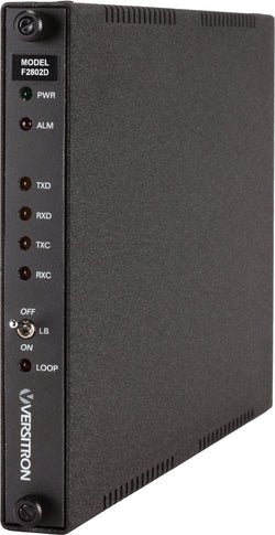
RS-232 Converter – Model F280XD
The Model F280xD products are fiber-optic modems designed to extend an RS-232 signal over fiber. These modems can also be used as a four channel synchronous/asynchronous data multiplexer, are DTE/DCE switch selectable, and interface with other VERSITRON FOM II series F28xxD Fiber Optic Modem, as well as VERSITRON M62xxD/M82xxD Fiber Optic MicroModems.
A Model F280xD link uses fiber optic cable of up to 2 Km for 1310nm multi-mode optics, and 20 Km for 1310nm single-mode optics. The link has a maximum data rate of 128Kbps, providing synchronous, asynchronous or isochronous full-duplex or simplex data trans-mission with fully transparent operation. The Model F280xD FOM II modems support the interface control signals associated with the EIA/TIA RS-232 or CCITT V.24/V.28, RS-423, and MIL-STD-188-114A standards. This is accomplished by multiplexing the control signals along with clock and data signals and transmitting this serialized signal to the remote unit. At the remote unit the signal is de-multiplexed and applied to the interface.
Data rate up to 128Kbps, DCE/DTE Switch Selectable, Terminal/Source Timing Option, and Eight Channel Data Multiplexer (Four in each direction). F280xD Modems have seven indicators: Power (PWR), Alarm (ALM), Transmit Data (TXD), Receive Data (RXD), Transmit Clock (TXC), Receive Clock (RXC), and Loopback (LOOP).
Product Features
- RS-232, RS-423, and MIL-STD-188-114A Standards
- Data Rate up to 128Kbps
- Full-Duplex or Simplex Transmission
- Source Timing or Terminal Timing
- Multiplexing Capable
- LED Indicators for Instant System Monitoring
- Four available Housing Options
- Standalone or Rack Mount
- SFP Fiber Optic Module Technology
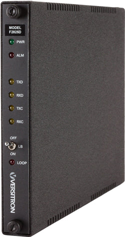
RS-530 Converter – Model F282XD
The Model F282xD products are fiber-optic modems designed to extend an RS-530 signal over fiber. These modems can also be used as a four channel synchronous/asynchronous data multiplexer, are DTE/DCE switch selectable, and interface with other VERSITRON FOM II series F28xxD Fiber Optic Modems, as well as VERSITRON M62xxD/M82xxD Fiber Optic MicroModems.
A Model F282xD link uses fiber optic cable of up to 2 Km for 1310nm multi-mode optics, and 20 Km for 1310nm single-mode optics. The link has a maximum data rate of 5 Mbps, providing synchronous, asynchronous or isochronous full-duplex or simplex data trans-mission with fully transparent operation. The Model F282xD FOM II modems support the interface control signals associated with the EIA/TIA RS-530, RS-422, RS-449, V.35, and MIL-STD-188-114A standards. This is accomplished by multiplexing the control signals along with clock and data signals and transmitting this serialized signal to the remote unit. At the remote unit the signal is de-multiplexed and applied to the interface.
Data rate up to 5 Mbps, DCE/DTE Switch Selectable, Terminal/Source Timing Option, and Eight Channel Data Multiplexer (Four in each direction). F282xD Modems have seven indicators: Power (PWR), Alarm (ALM), Transmit Data (TXD), Receive Data (RXD), Transmit Clock (TXC), Receive Clock (RXC), and Loopback (LOOP).
Product Features
- RS-530, RS-422, and MIL-STD-188-114A Standards
- Also supports RS-449 and V.35
- Data Rate up to 5 Mbps
- Full-Duplex or Simplex Transmission
- Source Timing or Terminal Timing
- Multiplexing Capable
- LED Indicators for Instant System Monitoring
- Four available Housing Options
- Standalone or Rack Mount
- SFP Fiber Optic Module Technology
Chassis & Accessories
|
Model
|
Description
|
|
HF-1 |
Single Card Enclosure |
|
HF-2SS |
2-Slot 19” Rack-Mount Chassis |
|
HF-20A |
20-Slot 19” Rack-Mount Chassis |
|
AC300WR |
Redundant Power Supply / System Monitor |
|
PSAC08 |
110VAC to 12VDC Power Adapter |
|
PSAC09 |
220VAC to 12VDC Power Adapter |
|
ADPHF01 |
Single-Slot Blank Panel for HF-2SS or HF-1 |
|
ADPHF02 |
Double-Slot Blank Panel for HF-20A Chassis |
Configuration Options
We encourage our customers to contact us by phone at 1-800-537-2296 or sales@versitron.com to discuss serial data applications. Let our experts help you with selecting the appropriate serial data modem and the installation option that would satisfy your requirement. We look forward to assisting with your project!